Look around the Graphics Lab
Regular, Semi-Regular Polyhedra, and thier Duals (first page)
Why I studied polyhedra, and Image Generation Techniques
![[photo]](ball_yel-grn.jpg)
Why I studied Polyhedra, and Image Generation Techniques
Why Polyhedra?
I started a personal study of polyhedra, originally for the purposes of working out a different designs for a giant wind filled "balls", as a ground display in my other hobby of kite flying (See my Kite Workshop). Normally kite fliers build such balls either as plain dodecahedron or a truncated icosahedron (the old soccer ball shape). Sometimes with short spikes added. I just wanted to do something different. (see photo)![[photo]](spikeball.jpg) My first "ball" (completed 1999) I built was based on a Great Stellated
Dodecahedron (see photo). Though the resulting ball worked fine, it was
disappointing as the spikes tended to cushion the ball, preventing it bouncing
around in the wind as it should. Not only that, I made a number of serious
mistakes in construction. With 10 panels coming together at a single point,
that point is extremely weak. As such the ball tends to "blow-out" and rip
when handled by kids.
You can find out more about this "Ball" in Anthony's Kite
Gallery (Balls).
My first "ball" (completed 1999) I built was based on a Great Stellated
Dodecahedron (see photo). Though the resulting ball worked fine, it was
disappointing as the spikes tended to cushion the ball, preventing it bouncing
around in the wind as it should. Not only that, I made a number of serious
mistakes in construction. With 10 panels coming together at a single point,
that point is extremely weak. As such the ball tends to "blow-out" and rip
when handled by kids.
You can find out more about this "Ball" in Anthony's Kite
Gallery (Balls).
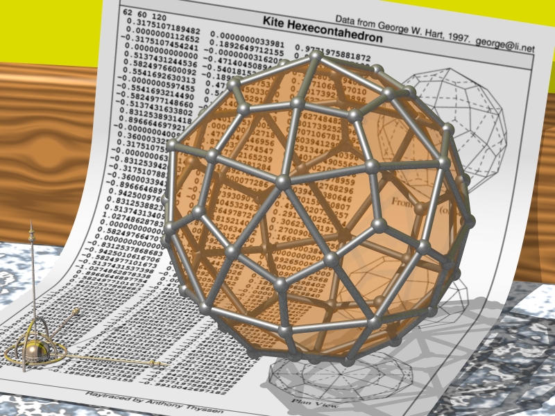
![[photo]](kiteball.jpg) My newest "ball" (completed May 2003) was a direct result of these studies.
When I saw the "Kite
Hexacontrahedron", I knew I found the object I wanted to use as a model. I
have never seen anyone use the kite shape for this purpose and it was so
suggestive that I had to use it for my project. The result was a 3.5 meter
ball made of 60 kite shaped pieces with seven red kites with yellow tails,
across a background of dark blue, sea green, and cyan. Lengths and angles of
the face was extracted and scaled from the data file.
My newest "ball" (completed May 2003) was a direct result of these studies.
When I saw the "Kite
Hexacontrahedron", I knew I found the object I wanted to use as a model. I
have never seen anyone use the kite shape for this purpose and it was so
suggestive that I had to use it for my project. The result was a 3.5 meter
ball made of 60 kite shaped pieces with seven red kites with yellow tails,
across a background of dark blue, sea green, and cyan. Lengths and angles of
the face was extracted and scaled from the data file.
I am thoroughly pleased with the result, as you can probably tell.
I also hoped to use the various polyhedral designs for other wind inflated objects. Things like: inflated tubes to hang off kite lines, medieval looking maces and so on.
Why publish another polyhedral library?
During my study of polyhedra, my interest branched all over the place. Into geometry, vector mathematics (resulting in my first CPAN perl module Math::VectorReal), 3D graphics, OFF format files, evenly distributing points on a sphere, polyhedral databases, OpenGL programming, and finally PovRay for displaying the results.I discovered George Hart's Encyclopedia of Polyhedra, which listed all the polyhedra I wanted, and even showed how George used polyhedra in his own art. This collection not only displayed images of the polyhedra, but also provides the data in the form of "VRML" files of the polyhedra, for interactive display of the object. He also lists good sources of viewers for this data.
There are a number of other ray-traced polyhedral collections on the WWW, though none as complete. And none except George Hart's, provide a means to actually get the data defining the object, (he provides VRML files with the data embedded).
Also many of these other collections do not display their polyhedra very well at all. I have even seen one collection, which was obviously ray-traced without any real supervision, resulting in some polyhedra appearing in the image with only a single face visible! As such when I started ray-tracing my polyhedra, I chose to use transparent faces, with metal edges, sort of like it is made from stained glass, to allow the back faces to also be visible.
So why did I decide to publish my own page, when George provides so much information? That was a big question, the only answer I have being, What the heck!. I also wanted to ensure the raw data I was using was also published with the objects, unlike the other collections. I am however constantly looking for better data sources, preferably with exact mathematical formula, or at least with the vertices, or faces aligned with the coordinate system.
The page is basically the final results of my experimentation with PovRay. And the various bits of information and findings I have made about polyhedra. I have a lot more, polyhedral objects which I have not published, so if you are interested contact me.
Polyhedral Naming
George Hart does often use alternative names for many of the polyhedra, particularly for the Archimedian Polyhedra. However I think his name changes are more to do with attempts to assign more mathematically correct names to the polyhedra, rather than common names given my many books on polyhedra.For example he does not use the term "anti-di-pyramid", or "anti-prism-duals" (polyhedra which look like pointy spindles) preferring "trapezohedra" instead.
It is his use of "trapezoidal" for objects which clearly do not have any trapezoids shaped faces, but are mathematical kite shaped faces. This includes his "trapezohedra" categorization! I renamed them appropriately on my own page.
Fair enough. The naming is only a label and often a number of names will describe the same object. For example the mathematically correct name for "cube" is actually "hexahedron", though it is hardly ever called that. :-)
See his pages on Polyhedra Names and his Glossary for George Harts own terminology.
Object File Formats
One of my big dislikes of most of the polyhedral collections I have seen on
the net was that while they provided great images of the polyhedra, they did
NOT provide the data used to create them! Generally they did not even discuss
the techniques used to display the generated objects. That is the parts that
would be most useful to someone wanting to make use of the information.
Without this basic information, it is very difficult to calculate the size and shape of the faces of the objects which you need to build models, of them. As such for each polyhedra images I display I also provide two extra data formats.
The VRML format is a link to that same polyhedra on George Hart's Web site (sometimes stored under a different name, see above). The file should be viewable (and rotatable) by adding a VRML version 1 compliant plug-in to your web browser. See George Harts page on VRML viewers to find something that will allow you to view the image.
ASIDE: I had a lot of trouble getting a free working VRML viewer for my linux machine, and actually created a viewer using perl filters to convert the VRML to OFF format (see below) and displaying that in a OpenGL OFF file displayer, that I wrote myself (Email me if you like to know more). I did eventually find a direct VRML viewer called "vrmlview", though it is huge in comparison to my simple OFF version.
The other format provided, OFF, is raw data I used to generate the polyhedra. The file format based on a plain "OFF" format (Object File Format), without any other extra data, like color or normals, you often find in other OFF file formats. Mind you the original OFF format was a more complex multi-file format, and just about everyone who uses this format redefines it slightly for their own use.
One such definition is given by Paul Bourke (See Off format definition).
Here is the exact format I am using, which excludes all optional color specifications, and the header keyword with its flags. To this I add some optional comment lines given the object name and data source...
| # Comments | Optional opening comments (prefixed by a "#"), the first comment line being the object title, the second (if present) marked "Data:" lists the source of data. |
| First Non-Comment Line | Three numbers: number of vertices (V), faces (F), and edges (E);
Which define the polyhedra in this file, and the rest of the file. |
| Vertex Coordinates | The X, Y and Z floating point location of each vertex.
The first line (second non-comment line in file) is vertex number 0 |
| Face Vertex Indexes | Each defining a flat polygonal face. The first number is the number of vertices forming the face, and the remaining integers are the indices into the previous vertex data table, that make up this face. |
| Edge Vertex Coords | Two vertex indices per line forming an edge to be displayed. |
This format is very usable by computers, being easy to read and process in just about any computer language.
Polyhedra Ray-tracing
To generate the images used on the page, I convert the OFF file into a set of data arrays parseable by the PovRay -- Persistence of Vision Ray-tracer. The generated "POV" scene data file consists of a set of arrays holding the object data (pre-scaled to fit into a unit sphere), and a set of external POVray macros then loop through that data, generating spheres (points), cylinders (edges), polygons and/or triangles (faces).After developing a "OFF" to "POV" filter (in perl), and a number of PovRay scene files to define how to display the generated object, it became relatively easy to create images of the polyhedra in whatever style I like.
The style I finally choose for these page, after a lot of experimenting, is a set of metallic rods and spheres for the vertices and edges (tinker-toy like). The faces are rendered as transparent "red" or "orange" glass, allowing the back faces, and background to be visible and to produce nice looking shadows.
The Polygon Problem..
The biggest problem I encountered in my ray-tracing, is that PovRay (and many other 3d object generators) can't handle polygons which aren't triangles! For example if you try to get the PovRay to draw a pentagon, all the vertices of the polygon MUST be co-planar to 13 decimal places!!!! If they aren't, PovRay throws a warning to this effect, and that polygon is effectively deleted from the image generated. :-(
Even if you define a polygon to 13 decimal places, rotating the object before passing the data to PovRay can be enough to make PovRay think the polygonal face is no longer "planer". Of course rotating the object within PovRay itself does not produce any problems, and is one such solution.
A number of solutions to the planar points problem exist...
- Triangulation...
-
A general solution is to subdivide your polygons into triangles, as
mathematically triangles define the "plane" they live in and thus their
vertices are always "co-planer". PovRay even defines a "triangle" primitive
for this very reason.
The triangles can be generated in a number of ways...
- Use a convex hull program on the polyhedras points, to generate the faces
(though ignore changes to your edge data). Hull programs generally by
default triangulate the larger polygons. This is simple and easy to do
with minor script processing of the hull output. However you do not have
much control of the process, depending as it does on the mathematical
errors in the vertex positions. It also will not work on polyhedra with
concave edges.
- Pick a vertex and generate a triangle with any edge for which that vertix
is not part of (EG: number of edges, minus 2 triangles, IE: 3 triangles
for a pentagon).
This is first of all not very symmetrical, and may produce some bad results (though I have not seen any). Also for a large polygon, you will probably end up with lots of long thin triangles. It will also only work for convex polygons.
- Pick the center point of the polygon (say average of vertices), and
triangulate with each edge (eg: 1 triangle for per edge). This will
generate 2 extra triangles than the previous simple method, but will
always be symmetrical and thus and texture mappings will also come out
better.
- Use a proper "triangulation function. This is probably the only solution
that will work correctly for concave polygons in the general case.
- Use a convex hull program on the polyhedras points, to generate the faces
(though ignore changes to your edge data). Hull programs generally by
default triangulate the larger polygons. This is simple and easy to do
with minor script processing of the hull output. However you do not have
much control of the process, depending as it does on the mathematical
errors in the vertex positions. It also will not work on polyhedra with
concave edges.
- Draw each face as a infinite plane...
-
Another approach to polygonal rendering with PovRay is to convert each face of
the object into a set of surface normals and distances from origin. Though
generating the correct normal vector can be a problem if your "face" is not
exactly flat, it is usually simpler.
These vectors can be used by PovRay to generate infinite planes from these normals at the appropriate distance from the origin. CSG (Computational Solid Geometry), can then be used to create the union of all these planes, so they cut each other to form the objects edges. Sort of like taking a large solid block of material and cutting the block across each of the polyhedras face.
One side effect of this is that the faces are defined completely independently of the defined vertices and edges. So if your mathematics is a long way off, they may not match up very well. In fact errors will become very noticeable at vertices involving four or more faces, such as a icosahedron. With care this should not be a problem, and in fact many OFF file formats I have seen often define these surface normals as extra data for this exact reason.
This technique however can only be used on convex polyhedra. On the other hand as CSG is used the object generated is actually "solid" within the virtual world PovRay is using! All the other methods generate a hollow object. This means that this method can be used for polyhedra which you later want to "dig holes" or "slice" into further pieces, for various special ray-traced effects.
I have used this method however, using the vertices themselves as the normal vector for each of the planes. This quickly generates a polyhedra's dual, in a very simple and easy way.
For example... Below is a dodecahedron, and its dual, a icosahedron, generated with this method. I left the small spheres of the vertices in place embeded in the generated plane to help show the vector producing each of the 12 faces. Actually it makes it look sort of 'Dalek' like (aka, "Dr Who and the Daleks").
![[photo]](platonic/dodecahedron.gif)
![[photo]](dodeca_dual.gif)
- Rotated Orthogonal Planes...
-
In email discussions with a John Cranmer, one way to ensure your polygons are
'flat' is to defined them in an orthogonal plane (such as the x-y plane) inside
the ray-traced scene itself. This will thus guarantee that the polygon will be
thought of by the ray-tracer as flat, and co-planer. The defined polygon can
then be translated and rotated into the right place to produce one face of the
polygon.
The method is akin to cutting out the polygonal faces using paper or cardboard and then taping them together to produce the desired model.
By defining them in the x-y plane in this way you reduced the need for very accurate 3d vertex positioning. Of course this will require a very different set of input data, as you not only need to define the polygon in x-y coordinates, but also the translation and rotation of that polygon to piece the object together.
John himself uses this successfully to generate the 59 stellations of the icosahedron, using polygon data published by Coxeter (H.S.M. Coxeter, Regular Polytopes, Dover reprint, 1973). As the polygons are properly defined, and the angles are well known, this was a rather easy solution for him.
![[photo]](platonic/dodecahedron.jpg)
![[photo]](dodeca_dual.jpg)
My Solution...
Currently before converting the OFF file data to PovRay data arrays, I filter it to triangulate any face that was not already a triangle. Note that only the face data is modified, adding more, simpler triangular faces to replace existing non-triangle faces. The edge data (detailing what edges are to be displayed), is left alone so that only the original edges of the off file are shown.
The triangulation method is currently the "Pick a vertex" method above. This however only works on convex polygons, and generally produces lots of long thin triangles. The advantage however is that no extra vertices are needed which means I don't have to deal with somehow defining extra "invisible" vertices in the OFF file when I then convert it to PovRay data arrays.
Thus in the display of the dodecahedron (see image above), each pentagon is sub-divided into three triangles, effectively increasing the number of faces defined in the PovRay data file from 12 pentagons, to 36 triangles.
PovRay however is better optimised to handle triangles than polygons, and I have yet to see any distortion in the generated image caused by this method. If I wanted to look for such a distortion, I'd probably render the surface as a mirror, reflecting the image of some detailed object (like the text I am including), to see if I can spot the artificial triangle boundaries. :-)
I would like to implement a proper triangulation algorithm so I can later deal with concave polygonal faces, but have not done so at this time.
Background Fluff - The A4 page
A single polygonal object on its own, does not make a good picture, and in a continual refinement, I have added "fluff" to the scene. Again something often forgotten by some polyhedral libraries on the www.When I first started I only used the "generic" checker pattern for the floor and back wall. Checks had a bonus value of providing unit measurements for scene generation, aiding the positioning of the objects, but as a background it looks very artificial. The checks were later replaced with a marble floor, and wooden panel.
Months later, I did more research to allow me to generate a virtual "A4" page of information. This A4 page is created by running the "OFF" file though the "a2ps" text to postscript filter. The first page of the postscript is then converted to PNG image format though the use of 'ImageMagick' and 'GhostScript'. The image is then read in by PovRay during the ray-tracing.
I did have a lot of problems trying to make that page "curve" nicely in the corner of the virtual world behind the polyhedron.
I tried quite a number of techniques, but finally found a PovRay macro file called "Bend.inc" on the web. This works great and even lets me haphazardly bend the page at odd angles. It does however make the image generation 20 times slower as straight flat page of text, as the single object is converted into hundreds of small thin slices by that macro sub-routine.
The "a2ps" filter was not the first method I tried, to convert the "OFF" text file to an image, but it proved better than anything else I have seen so far. It also added some interesting borders, and the ability to add a title, the data source, my own name and generation date at the bottom of the page. This extra detail was a real bonus as it meant looking though a directory of generated images is now lot easier.
I did say that this fluff was a continual process. For example the page in images (generated July 2001) looked rather grey. This has since been fixed with a much higher ambient lighting but not so much to destroy the shadows, and shading on the page (fixed June 2002).
The next improvement was the addition of a 2 dimensional line drawing of the object on the page. This was created using a Perl Script to rotate then generate a "fig" format line orthogonal view of the object. The 'fig' object was then exported to a image, and then the 'ImageMagick' programs allowed me to merge the diagram onto the A4 page during its conversion to a image for the ray-tracer to use, (added November 2002).
If all this seems a lot of work just background fluff. Your right! But the result I think was worth it. It was fun figuring out how to do it. I have even had comments from some non-computer friends that thought the image was a real photograph :-)
Other possible future refinement is to animate the polyhedra so it slowly rotates in the enlarged image. This of course means the larger image will have to be GIF rather than JPEG format.